
AWG5200 임의파형 발생기
| 대역폭 | DC to 4 GHz |
|---|---|
| 샘플링 속도 | up to 10 GS/s |
| 메모리 크기 | 2 GSample |
| 채널 수 | 8 채널 |
| 분해능 | 16 bit resolution |
AWG5200
AWG5200 임의 파형 발생기는 저렴한 가격으로 다중 장치 동기화를 통해 최대 32개 이상의 채널로 확장할 수 있으며, 높은 신호 충실도를 통해 까다로운 신호 발생이 가능합니다. 고급 연구, 전자 테스트 및 레이더, 전자전 시스템 설계 및 테스트에서 이상적입니다.

| 모델 | 아날로그 채널 | 수직 해상도 | 아날로그 대역폭 | 출력 주파수 | 최대 샘플 속도 | 정가 |
|---|---|---|---|---|---|---|
| AWG5202 | 2 | 16비트 | 2GHz(-3dB x) | DC 출력: 디퍼런셜1.5Vp-p /// AC 출력: -17 ~ -5dBm 싱글 엔드, BW 10MHz ~ 2GHz(기본) /// Amp AC 출력: -85 ~ +10dBm 싱글 엔드, BW 10MHz ~ 2GHz(옵션) | 1.5KS/s ~ 10GS/s(4GHz) | |
| AWG5204 | 4 | 16비트 | 2GHz(-3dB x) | DC 출력: 디퍼런셜1.5Vp-p /// AC 출력: -17 ~ -5dBm 싱글 엔드, BW 10MHz ~ 2GHz(기본) /// Amp AC 출력: -85 ~ +10dBm 싱글 엔드, BW 10MHz ~ 2GHz(옵션) | 1.5KS/s ~ 10GS/s(4GHz) | |
| AWG5208 | 8 | 16비트 | 2GHz(-3dB x) | DC 출력: 디퍼런셜1.5Vp-p /// AC 출력: -17 ~ -5dBm 싱글 엔드, BW 10MHz ~ 2GHz(기본) /// Amp AC 출력: -85 ~ +10dBm 싱글 엔드, BW 10MHz ~ 2GHz(옵션) | 1.5KS/s ~ 10GS/s(4GHz) |
Specifications
All specifications are typical unless noted otherwise. All specifications apply to all models unless noted otherwise.
Hardware characteristics
- Number of analog outputs
-
- AWG5202
- 2
- AWG5204
- 4
- AWG5208
- 8
- Analog output connector type
- SMA female
- Analog output impedance
- 50 Ω
- Number of marker outputs
-
- AWG5202
- 8
- AWG5204
- 16
- AWG5208
- 32
- Resolution (nominal)
- 16 bits with no markers active, 15 bits with 1 marker active, 14 bits with 2 markers active, 13 bits with 3 markers active, 12 bits with 4 markers active
- Waveform memory
- 2 GS/channel
- Waveform granularity
- 1 sample
- Waveform minimum size
- 2400 samples
- Run modes
-
- Continuous
- Waveform is continuously repeated
- Triggered
- Waveform is output only once after a trigger is received
- Triggered Continuous
- Waveform is continuously repeated after a trigger is received
- Gated
- Waveform is continuously repeated while the trigger is enabled
- Sample rate (nominal)
- 300 S/s to 5 GS/s (10 GS/s Interpolated - Double Data Rate)
- Sin(x)/x (-3dB)
- 2.22 GHz @ 5 GS/s, 4.44 GHz Interpolated @ 10 GS/s
Computer characteristics
- Operating system / peripherals / IO
- Microsoft® Windows OS
USB 2.0 compliant ports (2 front)
USB 3.0 compliant ports (4 rear)
RJ-45 Ethernet connector (rear panel) supports 10/100/1000BASE-T
VGA video (rear panel) for external monitor
eSATA (rear panel)
- Display characteristics
- LED backlit touch screen display, 165 mm (6.5 in.) diagonal, 1024 × 768 XGA
- Software driver for third-party applications
- IVI-COM driver
IVI-C driver
Analog output characteristics
- Effective frequency output
- Fmaximum (specified) is determined as "sample rate / oversampling rate" or "SR / 2.5".
- 2 GHz
4 GHz (Double Data Rate - DDR mode)
- DC High Bandwidth output
- Amplitude levels are measured as singled-ended outputs. Output doubles when using differential (both) outputs.
- Amplitude range
-
25 mVp-pto 0.75 Vp-p(single ended, 50 Ω terminated)
50 mVp-pto 1.5 Vp-p(differential mode, 100 Ω terminated)
- Amplitude accuracy (guaranteed)
-
±2% of setting ≥ 100 mVp-p
±5% of setting < 100 mVp-p
- Offset
- ±2 V (50 Ω into gnd), ±4 V into DC voltage terminated
- Offset accuracy
-
±(2% of |offset| + 10 mV); into 50 Ω to Gnd. (Common mode, guaranteed.)
±25 mV; into 100 Ω differential. (Differential mode.)
- Analog bandwidth
-
At 750 mVp-p: DC to 2 GHz (3 dB), DC to 4 GHz (6 dB)
- Rise/fall time
-
Rise/fall time measured at 20% to 80% levels.
< 110 ps at 1.5 Vp-psingle-ended termination
- DC High Bandwidth Amplified output (option)
- Amplitude levels are measured as singled-ended outputs. Output doubles when using differential (both) outputs.
- Amplitude range
-
25 mVp-pto 1.5 Vp-p(single ended, 50 Ω terminated)
50 mVp-pto 3.0 Vp-p(differential mode, 100 Ω terminated)
- Amplitude accuracy (guaranteed)
-
±2% of setting ≥ 100 mVp-p
±5% of setting < 100 mVp-p
- Offset
- ±2 V (50 Ω into gnd), ±4 V into DC voltage terminated
- Offset accuracy
-
±(2% of |offset| + 10 mV); into 50 Ω to Gnd. (Common mode, guaranteed.)
±25 mV; into 100 Ω differential. (Differential mode.)
- Analog bandwidth
-
At 750 mVp-p: DC to 2 GHz (3 dB), DC to 4 GHz (6 dB)
At 1.5 Vp-p: DC to 1.3 GHz (3 dB)
- Rise/fall time
-
Rise/fall time measured at 20% to 80% levels.
< 180 ps at 1.5 Vp-psingle-ended
- DC High Voltage output
- Amplitude levels are measured as singled-ended outputs. Output doubles when using differential (both) outputs.
- Amplitude range
-
10 mVp-pto 5.0 Vp-p(single ended, 50 Ω terminated)
20 mVp-pto 10.0 Vp-p(differential mode, 100 Ω terminated)
- Amplitude accuracy (guaranteed)
-
±2% of amplitude ≥ 160 mVp-p
±5% of amplitude < 160 mVp-p
- Offset
- ±2 V (50 Ω into gnd), ±4 V into high resistance or matching voltage terminated
- Offset accuracy
-
±(2% of |offset| + 1% of amplitude + 20 mV). (50 Ω-to-Gnd) (Common mode guaranteed.)
± 88 mV; into 100 Ω. (Differential mode.)
- Analog bandwidth
- DC – 370 MHz (3 dB) (at 2 Vp-p)
- Rise/fall time
-
Rise/fall time measured at 20% to 80% levels.
< 1.3 ns, at 5 Vp-psingle-ended.
< 1.1 ns, at 4 Vp-psingle-ended.
< 0.8 ns, at 3 Vp-psingle-ended.
< 0.6 ns, at 2 Vp-psingle-ended.
- AC Direct output
- Amplitude levels are measured as singled-ended outputs.
- Amplitude range
- -17 dBm to -5 dBm
- Amplitude accuracy
-
±0.5 dBm at 100 MHz
- DC bias
- ±5 V at 150 mA
- DC bias accuracy (guaranteed)
- ±(2% of bias + 20 mV); into an open circuit (zero load current)
- Analog bandwidth
- 10 MHz - 2 GHz (-3 dB), 10 MHz - 4 GHz (-6 dB)
- AC Amplified output (option)
- Amplitude levels are measured as singled-ended outputs.
- Amplitude range
-
-85 dBm to +10 dBm (10 MHz to 3.5 GHz)
-50 dBm to +10 dBm (>3.5 GHz to 5 GHz)
- Amplitude accuracy
-
±0.5 dBm at 100 MHz
- DC bias
- ±5 V at 150 mA
- DC bias accuracy (guaranteed)
- ±(2% of bias + 20 mV); into an open circuit (zero load current)
- Analog bandwidth
- 10 MHz - 2 GHz (-3 dB), 10 MHz - 4 GHz (-6 dB)
- Output match VSWR
-
-
Output path Specification DC High Bandwidth (including DCHB Amplified option) DC to 1 GHz < 1.25:1
1 GHz to 3 GHz < 1.9:1
3 GHz to 4 GHz < 2.3:1DC High Voltage DC to 400 MHz < 1.6:1
400 MHz to 1 GHz < 1.75:1
1 GHz to 2 GHz < 2.3:1AC Direct 10 MHz to 300 MHz < 2.0:1
300 MHz to 1.4 GHz < 1.6:1
1.4 GHz to 3 GHz < 2.2:1
3 GHz to 4 GHz < 2.5:1AC Amplified, +3 dBm 10 MHz to 500 MHz < 2.4:1
500 MHz to 1.5 GHz < 1.75:1
1.5 GHz to 4 GHz < 1.9:1
- Bit rate
- Bit rate determined as "sample rate / 4 points per cycle", allowing full impairment generation.
1.25 Gb/s at 5 GS/s
Channel timing characteristics
- Channel to channel skew (DC high bandwidth mode only)
-
±25 ps
- Skew adjust
-
- Range
- ±2 ns
- Resolution
- 250 fs
Sequencer characteristics
- Maximum sequencing steps
- 16,384
- Sub sequencing
- Single level of depth
Spurious Free Dynamic Range (SFDR) characteristics
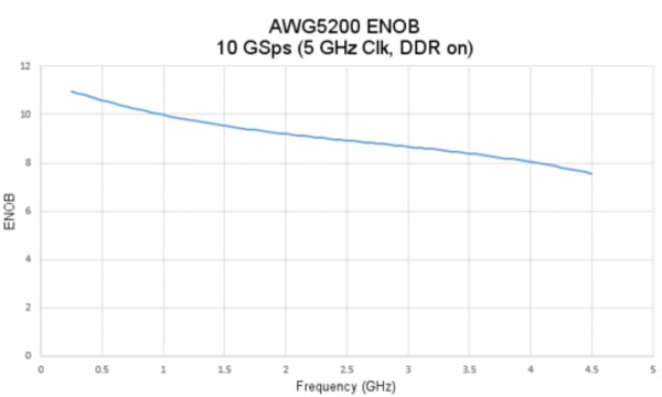
- Effective number of bits (ENOB)
-

- SFDR characteristics
-
SFDR is determined as a function of the directly generated carrier frequency.
Harmonics not included. Measured with a balun and with output amplitude set to 500 mV.
- DC High Bandwidth
-
500 mVpp
2.5 GS/s In band performance Adjacent band performance Analog channel output frequency Measured across Specification Measured across Specification 100 MHz 10 to <1250 MHz –80 dBc – – 10 to <155 MHz 10 to <1250 MHz –80 dBc – – 155 to <1000 MHz 10 to <1000 MHz –53 dBc 1000 to <1250 MHz –60 dBc 1000 to <1250 MHz 1000 to <1250 MHz –50 dBc 10 to <1000 MHz –50 dBc -
5 GS/s In band performance Adjacent band performance Analog channel output frequency Measured across Specification Measured across Specification 100 MHz 10 to <1250 MHz –80 dBc 1250 to <2500 MHz –75 dBc 10 to <310 MHz 10 to <1250 MHz –80 dBc 1250 to <2500 MHz –70 dBc 310 to <1250 MHz 10 to <1250 MHz –67 dBc 1250 to <2500 MHz –64 dBc
Specifications
All specifications are typical unless noted otherwise. All specifications apply to all models unless noted otherwise.
Hardware characteristics
- Number of analog outputs
-
- AWG5202
- 2
- AWG5204
- 4
- AWG5208
- 8
- Analog output connector type
- SMA female
- Analog output impedance
- 50 Ω
- Number of marker outputs
-
- AWG5202
- 8
- AWG5204
- 16
- AWG5208
- 32
- Resolution (nominal)
- 16 bits with no markers active, 15 bits with 1 marker active, 14 bits with 2 markers active, 13 bits with 3 markers active, 12 bits with 4 markers active
- Waveform memory
- 2 GS/channel
- Waveform granularity
- 1 sample
- Waveform minimum size
- 2400 samples
- Run modes
-
- Continuous
- Waveform is continuously repeated
- Triggered
- Waveform is output only once after a trigger is received
- Triggered Continuous
- Waveform is continuously repeated after a trigger is received
- Gated
- Waveform is continuously repeated while the trigger is enabled
- Sample rate (nominal)
- 300 S/s to 5 GS/s (10 GS/s Interpolated - Double Data Rate)
- Sin(x)/x (-3dB)
- 2.22 GHz @ 5 GS/s, 4.44 GHz Interpolated @ 10 GS/s
Computer characteristics
- Operating system / peripherals / IO
- Microsoft® Windows OS
USB 2.0 compliant ports (2 front)
USB 3.0 compliant ports (4 rear)
RJ-45 Ethernet connector (rear panel) supports 10/100/1000BASE-T
VGA video (rear panel) for external monitor
eSATA (rear panel)
- Display characteristics
- LED backlit touch screen display, 165 mm (6.5 in.) diagonal, 1024 × 768 XGA
- Software driver for third-party applications
- IVI-COM driver
IVI-C driver
Analog output characteristics
- Effective frequency output
- Fmaximum (specified) is determined as "sample rate / oversampling rate" or "SR / 2.5".
- 2 GHz
4 GHz (Double Data Rate - DDR mode)
- DC High Bandwidth output
- Amplitude levels are measured as singled-ended outputs. Output doubles when using differential (both) outputs.
- Amplitude range
-
25 mVp-pto 0.75 Vp-p(single ended, 50 Ω terminated)
50 mVp-pto 1.5 Vp-p(differential mode, 100 Ω terminated)
- Amplitude accuracy (guaranteed)
-
±2% of setting ≥ 100 mVp-p
±5% of setting < 100 mVp-p
- Offset
- ±2 V (50 Ω into gnd), ±4 V into DC voltage terminated
- Offset accuracy
-
±(2% of |offset| + 10 mV); into 50 Ω to Gnd. (Common mode, guaranteed.)
±25 mV; into 100 Ω differential. (Differential mode.)
- Analog bandwidth
-
At 750 mVp-p: DC to 2 GHz (3 dB), DC to 4 GHz (6 dB)
- Rise/fall time
-
Rise/fall time measured at 20% to 80% levels.
< 110 ps at 1.5 Vp-psingle-ended termination
- DC High Bandwidth Amplified output (option)
- Amplitude levels are measured as singled-ended outputs. Output doubles when using differential (both) outputs.
- Amplitude range
-
25 mVp-pto 1.5 Vp-p(single ended, 50 Ω terminated)
50 mVp-pto 3.0 Vp-p(differential mode, 100 Ω terminated)
- Amplitude accuracy (guaranteed)
-
±2% of setting ≥ 100 mVp-p
±5% of setting < 100 mVp-p
- Offset
- ±2 V (50 Ω into gnd), ±4 V into DC voltage terminated
- Offset accuracy
-
±(2% of |offset| + 10 mV); into 50 Ω to Gnd. (Common mode, guaranteed.)
±25 mV; into 100 Ω differential. (Differential mode.)
- Analog bandwidth
-
At 750 mVp-p: DC to 2 GHz (3 dB), DC to 4 GHz (6 dB)
At 1.5 Vp-p: DC to 1.3 GHz (3 dB)
- Rise/fall time
-
Rise/fall time measured at 20% to 80% levels.
< 180 ps at 1.5 Vp-psingle-ended
- DC High Voltage output
- Amplitude levels are measured as singled-ended outputs. Output doubles when using differential (both) outputs.
- Amplitude range
-
10 mVp-pto 5.0 Vp-p(single ended, 50 Ω terminated)
20 mVp-pto 10.0 Vp-p(differential mode, 100 Ω terminated)
- Amplitude accuracy (guaranteed)
-
±2% of amplitude ≥ 160 mVp-p
±5% of amplitude < 160 mVp-p
- Offset
- ±2 V (50 Ω into gnd), ±4 V into high resistance or matching voltage terminated
- Offset accuracy
-
±(2% of |offset| + 1% of amplitude + 20 mV). (50 Ω-to-Gnd) (Common mode guaranteed.)
± 88 mV; into 100 Ω. (Differential mode.)
- Analog bandwidth
- DC – 370 MHz (3 dB) (at 2 Vp-p)
- Rise/fall time
-
Rise/fall time measured at 20% to 80% levels.
< 1.3 ns, at 5 Vp-psingle-ended.
< 1.1 ns, at 4 Vp-psingle-ended.
< 0.8 ns, at 3 Vp-psingle-ended.
< 0.6 ns, at 2 Vp-psingle-ended.
- AC Direct output
- Amplitude levels are measured as singled-ended outputs.
- Amplitude range
- -17 dBm to -5 dBm
- Amplitude accuracy
-
±0.5 dBm at 100 MHz
- DC bias
- ±5 V at 150 mA
- DC bias accuracy (guaranteed)
- ±(2% of bias + 20 mV); into an open circuit (zero load current)
- Analog bandwidth
- 10 MHz - 2 GHz (-3 dB), 10 MHz - 4 GHz (-6 dB)
- AC Amplified output (option)
- Amplitude levels are measured as singled-ended outputs.
- Amplitude range
-
-85 dBm to +10 dBm (10 MHz to 3.5 GHz)
-50 dBm to +10 dBm (>3.5 GHz to 5 GHz)
- Amplitude accuracy
-
±0.5 dBm at 100 MHz
- DC bias
- ±5 V at 150 mA
- DC bias accuracy (guaranteed)
- ±(2% of bias + 20 mV); into an open circuit (zero load current)
- Analog bandwidth
- 10 MHz - 2 GHz (-3 dB), 10 MHz - 4 GHz (-6 dB)
- Output match VSWR
-
-
Output path Specification DC High Bandwidth (including DCHB Amplified option) DC to 1 GHz < 1.25:1
1 GHz to 3 GHz < 1.9:1
3 GHz to 4 GHz < 2.3:1DC High Voltage DC to 400 MHz < 1.6:1
400 MHz to 1 GHz < 1.75:1
1 GHz to 2 GHz < 2.3:1AC Direct 10 MHz to 300 MHz < 2.0:1
300 MHz to 1.4 GHz < 1.6:1
1.4 GHz to 3 GHz < 2.2:1
3 GHz to 4 GHz < 2.5:1AC Amplified, +3 dBm 10 MHz to 500 MHz < 2.4:1
500 MHz to 1.5 GHz < 1.75:1
1.5 GHz to 4 GHz < 1.9:1
- Bit rate
- Bit rate determined as "sample rate / 4 points per cycle", allowing full impairment generation.
1.25 Gb/s at 5 GS/s
Channel timing characteristics
- Channel to channel skew (DC high bandwidth mode only)
-
±25 ps
- Skew adjust
-
- Range
- ±2 ns
- Resolution
- 250 fs
Sequencer characteristics
- Maximum sequencing steps
- 16,384
- Sub sequencing
- Single level of depth
Spurious Free Dynamic Range (SFDR) characteristics
- Effective number of bits (ENOB)
-
- SFDR characteristics
-
SFDR is determined as a function of the directly generated carrier frequency.
Harmonics not included. Measured with a balun and with output amplitude set to 500 mV.
- DC High Bandwidth
-
500 mVpp
2.5 GS/s In band performance Adjacent band performance Analog channel output frequency Measured across Specification Measured across Specification 100 MHz 10 to <1250 MHz –80 dBc – – 10 to <155 MHz 10 to <1250 MHz –80 dBc – – 155 to <1000 MHz 10 to <1000 MHz –53 dBc 1000 to <1250 MHz –60 dBc 1000 to <1250 MHz 1000 to <1250 MHz –50 dBc 10 to <1000 MHz –50 dBc -
5 GS/s In band performance Adjacent band performance Analog channel output frequency Measured across Specification Measured across Specification 100 MHz 10 to <1250 MHz –80 dBc 1250 to <2500 MHz –75 dBc 10 to <310 MHz 10 to <1250 MHz –80 dBc 1250 to <2500 MHz –70 dBc 310 to <1250 MHz 10 to <1250 MHz –67 dBc 1250 to <2500 MHz –64 dBc
INFORMATION
상호 : 주식회사 알트로닉스 주소 : 서울특별시 금천구 가산디지털2로 101, 한라원앤원타워 B동 1401호 Tel : 02-2101-2140 Fax : 02-2101-2142
사업자등록번호 : 292-88-01789
사업자등록번호 : 292-88-01789
Copyright © 2019 주식회사 알트로닉스. All Rights Reserved.
designed by website.co.kr