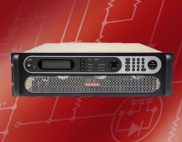

Sorensen SG Series Specifications
| Common | |
| Remote Sense | Terminals are provided to sense output voltage at point of load. Maximum line drop 5% of rated voltage per line f |
| Parallel Operation | Up to 5 units may be paralleled for additional current within the power supply single-unit specifications, with exception of the DC output current set accuracy. Additional paralleled SG units will add 0.3% inaccuracy per unit. To parallel more than 5 units, contact factory. |
| Series Operation | Up to 2 units (see Output Float Voltage) |
| Input | |
| Nominal Voltage 3 phase, 3 wire + ground |
208/230 VAC (operating range 187 - 253 VAC) 380/400 VAC (operating range 342 - 440 VAC) 440/480 VAC (operating range 396 - 528 VAC) |
| Frequency | 47 – 63Hz , 400Hz ( 400Hz @ 208VAC, for 6U units is optional modification and does not carry CE, UL or CSA markings ) |
| Power Factor | >0.9 typical for 10V - 30V, 50V, 1000V and other models with optional “PF” modification. >0.75 typical for 208/220 VAC input (40V, 60V - 800V models, 0.9 available with modification “PF”) >0.72 typical for 380/480 VAC input (40V, 60V - 800V models, 0.9 available with modification “PF”) >0.69 typical for 440/480 VAC input (40V, 60V - 800V models, 0.9 available with modification “PF”) |
| Protection | ½ cycle ride-though , typical, on all three phases, 3 cycle ride through on single phase; missing phase shutdown ( 800V model 6.4 msec on all 3 phases ) |
| Programming & Read-back Specifications ( with sense wires used ) | |||||
| Programming | Read-Back / Monitoring | ||||
| Accuracy | Resolution | Accuracy | Resolution | ||
| Front panel Display |
SGA: +/- (0.5%fs + 1 digit) SGI (40-1000V) +/- 0.1% of voltage at full scale SGI (40-1000V) +/- 0.4% of current at full scale |
SGA: 3.5 digits SGI: 4.0 digits |
SGA: +/- (0.5%fs + 1 digit) SGI, Voltage: +/- 0.1% of full scale SGI, Current: +/- 0.4% of full scale |
SGA: 3.5 digits SGI: 4.0 digits | Knob control & Display read-back |
| SGI (10-30V) 0.1% of set point +0.1% of voltage rating SGI (10-30V) 0.1% of set point +0.4% of current rating | SGI (10-30V) 0.1% of actual +0.15% voltage rating | ||||
| Remote Analog Interface | Voltage +/-0.25% of full scale Current (40-1000V) 0.8% of full scale , (10-30V) 1.0% of full scale | N/A |
(40-1000V) +/-1.0% of full scale |
N/A | 25-pin D-sub connector (0~5 V or 0~10 V) |
| (10-30V) +/-0.5% of full scale | |||||
| Remote Digital Interface | Voltage: +/- 0.1% of full scale, Current: +/- 0.4% of full scale | +/-0.002% of full scale | Voltage: +/- 0.1% of full scale Current: +/- 0.4% of full scale |
+/-0.002% of full scale | RS-232C (Standard on SGI), Optional IEEE-488.2 and Optional LXI Compliant 10/100 base-T Ethernet (see Options) |
| OVP | +/- 1% of full scale | +/-0.002% of full scale | Programming range: 5-110% Configured from front panel, remote analog or via optional digital inputs | ||
| User I/O | Disconnect & Polarity-reversal relay control ( Only available with Ethernet Option ) | Digital 10-pin Molex type connector Chart Below | |||
| Software | IVI & CVI drivers available under DOWNLOADS at: www.ProgrammablePower.com | ||||
| Physical | |||
| 3U Models (10V-30V) | 3U Models (40V-1000V) | 6U Models (60V-600V) | |
| Width | 19.00 in (48.3 cm) | 19.00 in (48.3 cm) | 19.00 in (48.3 cm) |
| Depth | 28.09 in (71.35 cm) | 26.4 in (67.1 cm) | 27.06 in (68.8 cm) |
| Height | 5.25 in (13.3 cm) | 5.25 in (13.3 cm) | 10.5 in (26.7 cm) |
| Weight |
(4kW, 10V 15V) ≈<65 lbs (29 kg) |
(5kW) ≈ ≤60 lbs (27 kg) |
(20kW) ≈ ≤140 lbs (64 kg) |
| Shipping Weight | Contact factory for more product & shipping weights | ||
| Output | ||||
| Ripple & Noise (Voltage Mode, Typical) | See Output: Voltage & Current Ranges Chart above. Ripple and noise specified at full load, nominal AC input. Noise measured with 6ft. cable, 1μf at load | |||
| Output Rise Time (40-800V) | ≈< 100 ms 5-95% of full scale typical - resistive load (Contact factory for model specific slew rates) | |||
| Output Rise Time (10-30V) |
Rise Time, ms, MAX | Condition | ||
| 10 | Measured from 10% to 90% of the output voltage change - resistive load, typical | |||
| Output Voltage Fall Time (10-30V) |
Fall Time, MS MAX | Condition | ||
| No Load 1 50 |
100% CC Load 10 | 100% CR Load 10 | Measured from 90% to 10% of the output voltage change. - resistive load, typical | |
| Output Current Rise Time (10-30V) |
Rise Time, ms, MAX | Condition | ||
| 20 | Measured from 10% to 90% of the output current change - resistive load, typical | |||
| Output Current Fall Time (10-30V) |
Rise Time, ms, MAX | Condition | ||
| 10 | Measured from 90% to 10% of the output current change - resistive load, typical | |||
| Line Regulation (with sense wires used) | (±10% of nominal AC input, constant load) Voltage Mode: +/- 0.01% of full scale (40-800V) Current Mode: +/- 0.05% of full scale (40-800V) Voltage Mode and Current Mode: +/- 0.05% of full scale (10-30V) |
|||
| Load Regulation (with sense wires used) | (no load to full load, nominal AC input) Voltage Mode: +/- 0.02% of full scale (40-800V) Current Mode: +/- 0.1% of full scale Voltage Mode: +/- 0.05% of full scale (10-30V) |
|||
| Load Transient Response | Recovers within 1ms to +/-0.75% of full-scale of steadystate output for a 50% to 100% or 100% to 50% load change | |||
| Efficiency | 87% typical at nominal line and max load | |||
| Stability | ±0.05% of set point after 30 minute warm-up and over 8 hours at fixed line, load and temperature, typical | |||
| Temperature Coefficient | 0.02%/ C of maximum output voltage rating for voltage set point, typical 0.03%/ C of maximum output current rating for current set point, typical |
|||
| Output Float Voltage | Negative terminal within +/- 300 V of chassis potential. (We recommend the use of optional isolated analog Interface (IAI).) Supplies in "series" should be the same output voltage/current, in not system current is limited to lower of the two supplies. |
|||
| Environmental | |
| Operating Temperature | 0 to 50º C |
| Storage Temperature | -25º C to 65º C |
| Humidity Range | Relative humidity up to 95% non-condensing, 0º C – 50º C |
| Altitude | Operating full power available up to 5,000 ft. (~1,500 m), derate 10% of full power for every 1,000 feet higher; non-operating to 40,000 ft. (~12,000 m) |
| Cooling | Front and side air inlet, rear exhaust. Temperature controlled, variable speed fans. Units may be stacked without spacing. |
| Regulatory | Certified to UL/CSA 61010 and IEC/EN 61010-1 by a NRTL, CE Compliant, Semi-F47 Compliant. LVD Categories: Installation Category II: Pollution Degree 2; Class II Equipment: for Indoor Use Only, back panel not user accessible (see user manual for installation instructions) EMC Directive, EN 61326:1998 |
| Front Panel Dust Filter | 30 PPI (Pores Per Inch) - must ensure adequate airflow and / or derate max. temperature. 3U unit only. |
| Output: Voltage and Current Ranges | |||
| 3U | |||
| Power | 4/5 kW | 8/10 kW | 12/15 kW |
| Voltage | Current | ||
| 10 | 400 | 800 | 1200 |
| 15 | 267 | 534 | 801 |
| 20 | 250 | 500 | 750 |
| 30 | 167 | 334 | 501 |
| 40 | 125 | 250 | 375 |
| 50 | 100 | 200 | 300 |
| 60 | 83 | 167 | 250 |
| 80 | 63 | 125 | 188 |
| 100 | 50 | 100 | 150 |
| 160 | 31 | 63 | 94 |
| 200 | 25 | 50 | 75 |
| 250 | 20 | 40 | 60 |
| 300 | 17 | 33 | 50 |
| 330 | 15 | 30 | 45 |
| 400 | 12 | 25 | 38 |
| 500 | 10 | 20 | 30 |
| 600 | 8 | 17 | 25 |
| 800 | 6.2 | 12.5 | 18.7 |
| 1000 | 5 | 10 | 15 |
| Output: Voltage and Current Ranges | |||
| 6U | |||
| Power | 16/20 kW | 20/25 kW | 24/30 kW |
| Voltage | Current | ||
| 10 | 1600* | 2000* | 2400* |
| 15 | 1068* | 1335* | 1602* |
| 20 | 1000* | 1250* | 1500* |
| 30 | 668* | 835* | 1002* |
| 40 | 500* | 625* | 750* |
| 50 | 400* | 500* | 600* |
| 60 | 333 | 417 | 500 |
| 80 | 250 | 313 | 375 |
| 100 | 200 | 250 | 300 |
| 160 | 125 | 156 | 188 |
| 200 | 100 | 125 | 150 |
| 250 | 80 | 100 | 120 |
| 300 | 67 | 83 | 100 |
| 330 | 61 | 76 | 91 |
| 400 | 50 | 63 | 75 |
| 500 | 40 | 50 | 60 |
| 600 | 33 | 42 | 50 |
| 800 | 25* | 31.2* | 37.5* |
| 1000 | 20* | 25* | 30* |
| * By way of paralleling 5kW, 10kW & 15kW supplies | |||
| Read-back Specifications | |||
| Ripple & Noise | |||
| Voltage | rms (20Hz-300kHz) | p-p (20Hz - 20MHz) | |
| 10 | 20mV | 50mV | |
| 15 | 20mV | 50mV | |
| 20 | 20mV | 60mV | |
| 30 | 20mV | 60mV | |
| 40 | 20mV | 75mV | |
| 50 | 20mV | 75mV | |
| 60 | 20mV | 75mV | |
| 80 | 20mV | 100mV | |
| 100 | 20mV | 100mV | |
| 160 | 25mV | 150mV | |
| 200 | 25mV | 175mV | |
| 250 | 30mV | 200mV | |
| 300 | 30mV | 200mV | |
| 330 | 30mV | 200mV | |
| 400 | 30mV | 300mV | |
| 500 | 50mV | 350mV | |
| 600 | 60mV | 350mV | |
| 800 | 80mV | 500mV | |
| 1000 | 100 mV | 650 mV | |
| * By way of paralleling 5kW, 10kW & 15kW supplies | |||
| Analog User I/O Pinouts | |||
| 1 | Isolated Remote ON/OFF | 14 | Isolated TTL/CMOS ON/OFF Control |
| 2 | Isolated Circuit Return | 15 | Remote Voltage Programming |
| 3 | Remote Overvoltage Set | 16 | Remote Current Programming |
| 4 | Voltage Return for Pins 9, 15, or 21 | 17 | Fault State |
| 5 | Remote ON/OFF | 18 | Shutdown Fault |
| 6 | Circuit Common | 19 | Output Voltage Monitor |
| 7 | Output Current Monitor | 20 | Voltage Return for Pins 9, 15, or 21 |
| 8 | Local Voltage Control Monitor | 21 | Voltage Control Resistance |
| 9 | Remote Voltage Programming | 22 | Current Control Resistance |
| 10 | Remote Current Programming | 23 | Current Return for Pins 10, 16, or 22 |
| 11 | Local Current Control Monitor | 24 | Circuit Common |
| 12 | Not Used | 25 | Current Return for Pins 10, 16, or 22 |
| 13 | Not Used | ||
| Digital User I/O Pinouts ( Ethernet Option Only ) | |||
| 1 | Fold Back Monitor | ||
| 2 | Direct Shutdown | ||
| 3 | Fault Indication | ||
| 4 | Trigger Out | ||
| 5 | Common | ||
| 6 | Polarity output reversal signal | ||
| 7 | Isolation relays relay open signal | ||
| 8 | Sense relays open signal | ||
| 9 | Common | ||
| 10 | Trigger in | ||
