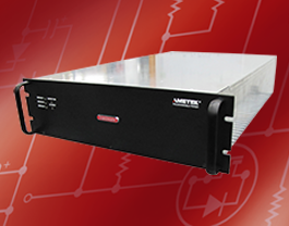
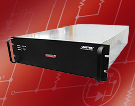
Sorensen ASD Series Specifications
| Input | |||
| Voltage Ranges | 342VAC to 440VAC (model D). Nominal rating is 380/400VAC. 432VAC to 528VAC (model E). Nominal rating is 480VAC |
||
| Frequency | Rated 47 through 63 Hz | ||
| Efficiency | >91% (typical), nominal line, full load. | ||
| Max Current, per phase, low line |
400/380Vac | 480Vac | |
| 10kW unit (1 module) | 21Arms | 17Arms | |
| 20kW unit (2 modules) | 42Arms | 33Arms | |
| 30kW unit (3 modules) | 63Arms | 50Arms | |
| Current Inrush | 200A Typical | ||
| Power Factor | >0.9 @ Full Load and at nominal line | ||
| Brownout Provisions | Designed to meet SEMI F47-0706, S3, S8, S14 at nominal input voltages | ||
| Output | |||||
| Voltage Output | 10kW | 20kW | 30kW | Noise (pk-pk) *** | Noise (RMS) *** |
| 40Vdc | 250A | 500A | 750A | 150mV | 40mV |
| 60Vdc | 167A | 334A | 501A | 150mV | 40mV |
|
(*) Measured at the load terminals, with 1uF in parallel and 6ft of low-inductance load cable with supply operating at full load and nominal input line voltage. |
|||||
| Sense | To compensate load cables voltage drop, units can generate 2% additional voltage at full scale of output voltage. | ||||
| Output | |
| Load Regulation (Specified at No load to Full load change, nominal AC input) | |
| Voltage | 0.1% of maximum output voltage/ current |
| Current | 0.1% of maximum output voltage/ current |
| Line Regulation (Specified at ±10% of nominal AC input, constant load) | |
| Voltage | 0.05% of maximum output voltage/ current |
| Current | 0.05% of maximum output voltage/ current |
| Transient Response | A 50% step load will recover to within 0.75% of original value within 1mSec |
| Stability | ±0.05% of set point after 8 hrs. at fixed line, load and temperature. After 30min warm-up. |
| Analog Remote Programming | |
| Voltage Accuracy | 0.5% of full scale |
| Current Accuracy | 1% of full scale |
| Power Accuracy | 1.5% of full scale |
| Voltage Monitoring | 0.5% of full scale |
| Current Monitoring | 1% of full scale |
| Power Monitoring | 1.5% of full scale |
| Programming range | 0-10Vdc, 4-20mA |
| Output | |
| Output Float | Units maybe put in series with the float limit of output terminals must be within ±150V of chassis potential |
| Parallel | Multiple units can be paralleled to form higher power systems. Chassis control loops are tied together so that resulting higher power systems have the same transient response as a 30kW system. Control commands are only required to be sent to "master" supply. Parallel supplies require a shielded CAT 5 cable (STP) and appropriate output wiring connections by the user. |
| Calibration | End user calibration is supported. All standard and digital calibration can be performed without removing covers. |
| Digital Control (Optional) | Ethernet (Modbus-TCP or Ethernet/IP), RS-485 (MODBUS-RTU) |
| Analog Control | All control signals are isolated from the outputs |
| Advanced Digital Features (Requires Optional Digital Control) | |
| Graphical User Interface | Graphical User Interface (Windows based) enables remote control and display of the supply operation including the a dvanced features listed below |
| Oscilloscope Function (125 Hz) |
Up to two parameters; Voltage, current, output impedance, output cable impedance, output cable voltage drop, power delivered… |
| Data logging | Programmable update rate of 1 sec to 1000 sec (default 10 sec) with last 1000 points stored. Stored parameters include, output voltage/current, programmed set points, input voltage, output impedance, cable impedance, total power deliver, power meter, internal faults |
| System fault reporting | Outside of set point, output impedance (detection of cabling, connection or load problems) |
| Physical | |||
| 30 kW | 20 kW | 10 kW | |
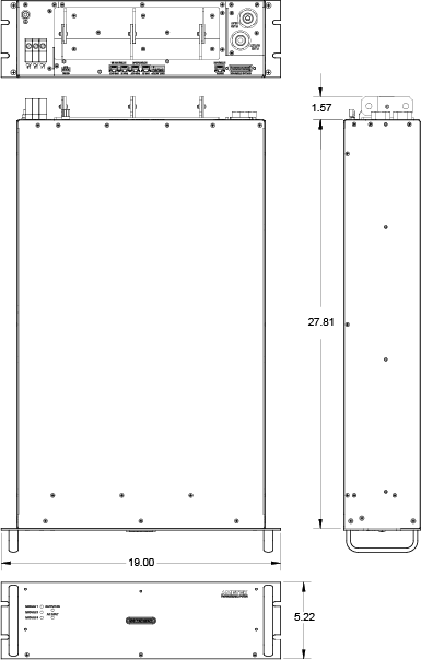
| Width | 19.00in (48.3cm) | 19.00in (48.3cm) | 19.00in (48.3cm) |
| Depth | 30.00" (76.2 cm) | 30.00" (76.2 cm) | 30.00" (76.2 cm) |
| Height | 3U-5.22" rackmount (13.25 cm) | 3U-5.22" rackmount (13.25 cm) | |
| Weight | ≤125 lbs (56.69 kg) | ≤125 lbs (56.69 kg) | ≤125 lbs (56.69 kg) |
| Shipping Weight | Contact factory for more product & shipping weights | ||
| Mounting provisions | EIA rack-mount with slide provisions. Recommended rack slide: Jonathan slide, P/N 370EZ-28 | ||
| AC Input Connector | Phoenix Contact terminal block | ||
| Protective Ground | 1/4-20 stud | ||
| Output Connectors | bus bars with 3/8-16 inserted PEM nuts | ||
| Water Connections | 3/8-18 NPTF hex bulkhead | ||
| Ambient Temperature | 0 to 50ºC | ||
| Humidity | Relative humidity up to 95%, non-condensing | ||
| Water cooling specifications | |
| Flow | 1.5 gpm nominal, 1.25gpm minimum, 1.75gpm maximum. Internal condensation must be prevented by ensuring that the temperature of the coolant is sufficiently high compared with the ambient air dew point |
| Temperature | 25ºC nominal, 20ºC minimum, 30ºC maximum |
| Maximum pressure | 80 PSI |
| Pressure drop | typical 12 PSI @ 1.5gpm per chassis |
| Regulatory |
| Certified to UL/CSA 61010 and IEC/EN 61010-1 by a NRTL, CE Compliant, LVD Categories: Installation Category II: Pollution Degree 2; Class II Equipment: for Indoor Use Only. Rack mount equipment requires proper enclosure provided in end use. EMC Directive, EN 61326:1998 |


